
Testuojam https://www.savel.org
There are lots of China made LED board with HUB08 connector. Boards typically are single or two color ones, without variable brightness. Boards can be connected in daisy chain mode using 16 pin connector. There are specialized MCU boards from China with very ugly, sometimes password protected software. For custom use there are some bad coded Arduino “libraries”, but there is no protocol description. We will try to fill this gap and analyze China made controller and will connect some boards to STM32F103 “Blue pill” board.
The connector is standard 0.1″, 16 pin connector:
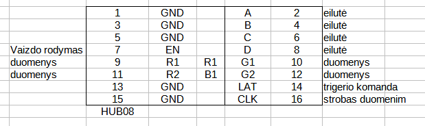
7 – EN, enable image; 9,10,11,12 – data input; 14 -latch (transfer data from SPI register to output register; 16 – SPI clock; 2,4,6,8 – select current line to show, total 16 lines.
General timing of the interface:
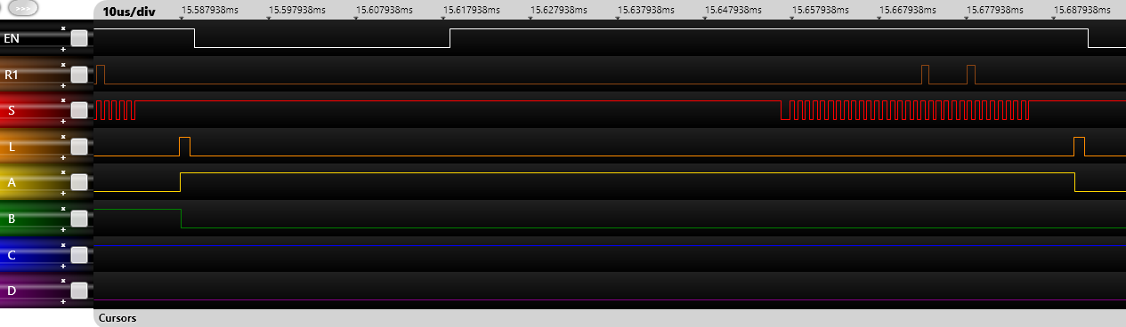
SPI clock was about 1.2MHz, horizontal line refresh ~11kHz.
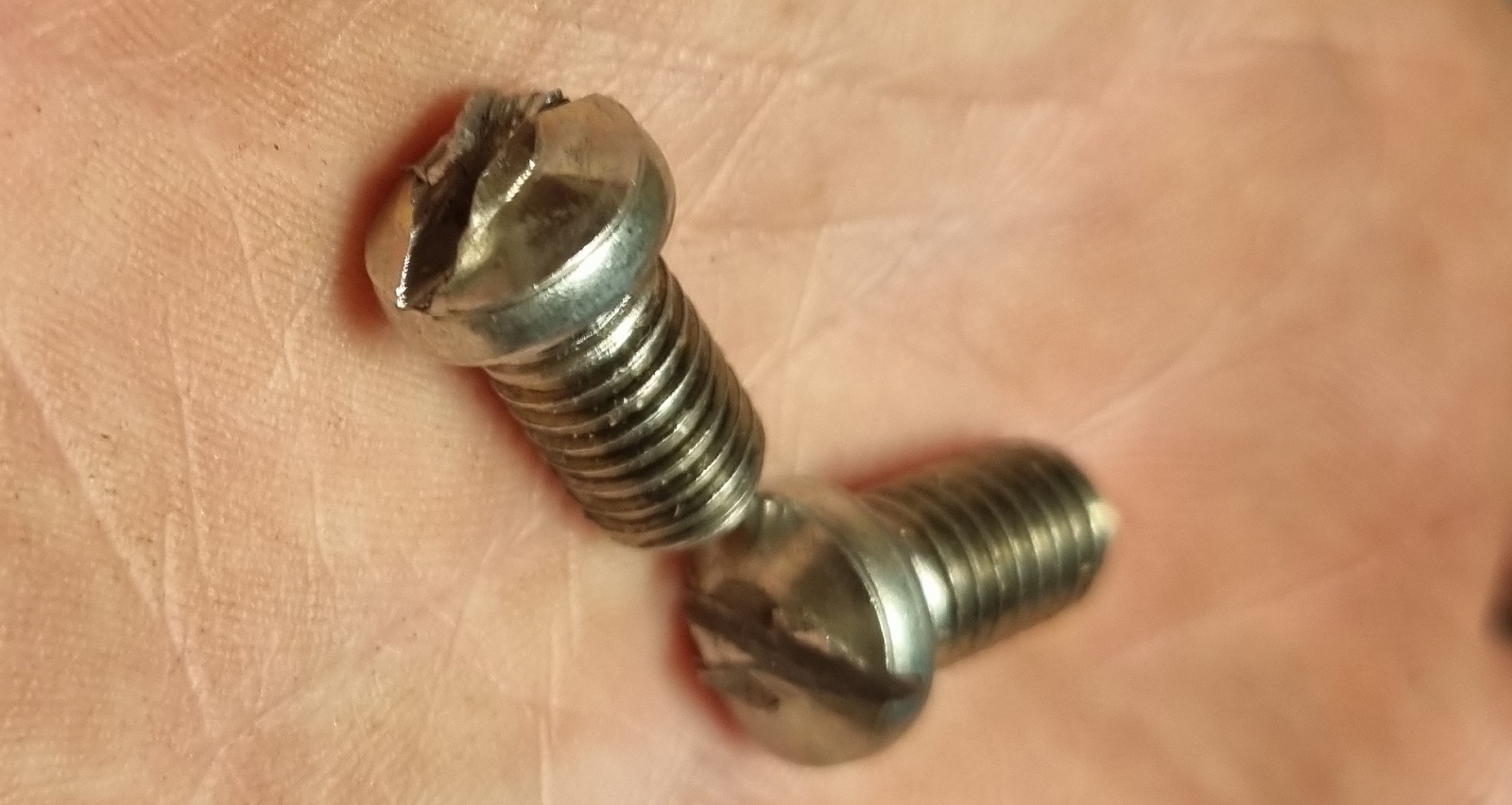
How it works: transfer via SPI some pixel data (up to 4 channels), send short LATCH command (74HC595) to transfer data and for some time enable EN to show line. The LED boad has hardware protection for stalled data transfer. If static data are detected, the output is disabled. To keep image on the board the clocks must be active.
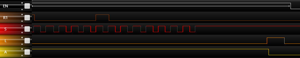
Clock timings details.
There are two ways to create image on the LED matrix board: dynamic creation of the image and transfer from video RAM. First method saves lots of RAM, but there must be very strict timing, like in Atari 2600. Second method is much easier, but we need video RAM.
For our experiment I decided to use video RAM method. I connected two boards in 64×64 pixel (LED) configuration.
As “Blue pill” board’s MCU has only one channel SPI (STM32F103c8t6) I made some strange connections on the LED boards- all SPI data lines are connected in series: Data from the MCU goes to R2 of the first board, R2 output from first board returns to R1 of same, first board. Output R1 of first board goes to R2 input of second board. R2 output returns to R1 input. Now we have 4 rows of 64 LEDs int the single logical row. We need transfer the data for 4×64 LEDs (bits), total 32 bytes of data. And repeat this for 16 lines. Total we need 512 bytes of the video RAM.
All Hub08 interface is interrupt driven: first we use timer interrupt for line start (Horizontal sync). In this interrupt we calculate video RAM addres and transfer 32 byte via SPI using HAL routines (somehow DMA SPI is not working! Maybe some error or fake chip on this PCB). How we wait for SPI finish interrupt. Here we select LED row, enable output, change some variables for the software interrupts and return control to the main program.
All software and source code:
Hub08 LED board interface with STM32F103 Blue pill source code and compiled HEX file.
Hub08 software have only the basic functions: plot and point (setting the point and reading color of the point from video RAM).
I have small collection of vintage computers. Several computers do not have PSU, other one have very specific ones. The problem is with some that looks like “standard”, have same connector like others, but have reversed polarity. Like ZX Spectrum or Commodore 16.
I decided to introduce some standard for my collection:
To prevent reverse polarity, computer may have serial diodes, rectifier bridges installed.
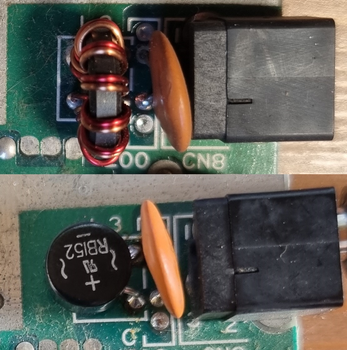
Silicon rectifier installed in Commodore 16.
To prevent polarity errors it is possible to use 3..5A diode to short power input (assuming that PSU bricks are <3A).
There is classic basic program for Commodore 64 computer to print maze on the screen. This program random prints “/” and “\” character on screen. I wanted to implement same program on modern computer and print the result. Not only to print, but also, use print preview.
Original C64 program:
10 PRINT CHR$(205.5+RND(1)); : GOTO 10
After some investigation I found in the internet the best option for MS Visual Studio Express VB (.net). This software “set” allows to print the same stuff to windows form image, printer preview control or to real printer output. This is not very straight, with some hack, but source code is self explanative. Thanks to MS for making it so strange.
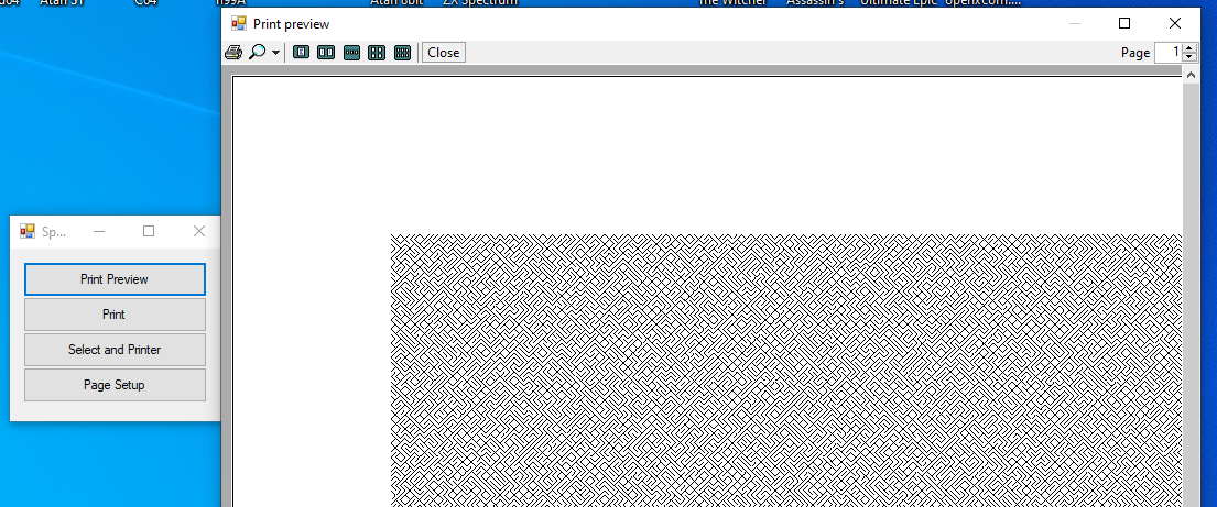
Program is very simple- demo button to invoke various types of functions: print, printer setup, page setup, print preview… With small change it is posible to use same graphics commands to picturebox object.
Visual Studio Express VB Source code.
Program read “page setup” settings and adjust parameters for print. Still there is bug when changing paper orientation, but I think it is solvable.
I was testing old Amiga computer and noticed, that somewhere I lost the mouse. It is proprietary mouse for Amiga computer, it even does not work with Atari ones. The mouse itself is very simple- only raw quadrature information is sent (mouse buttons are on separate wires). This make mouse very simple, but it uses 8 wire cable! (9 with middle button).
I was thinking, that I might find some ball mouse for PC computer, remove controller and will build exact replica of the Amiga mouse. But ball mouses are rare. Instead I found several optical mouses, the old ones, with two chips inside.
The first mouse was USB one, with Avago chip:
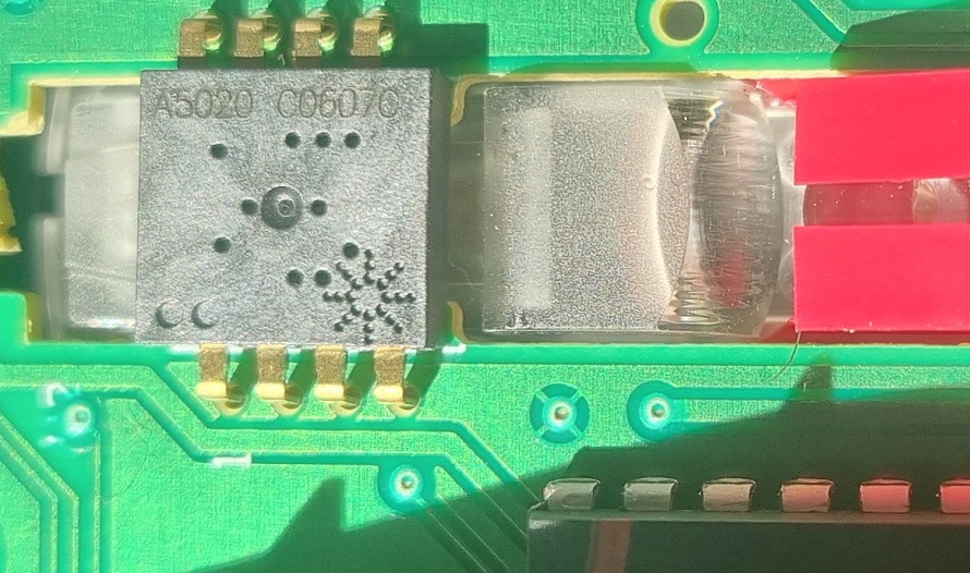
The chip is ADNS-5020, from Avago.
This chip has SPI interface, too modern for our goals.
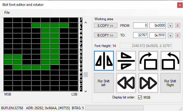
This is small tool writtent in Visual Studio Express VB. Main purpose of this tool is to find 8 bit wide fonts and graphics in various ROM, firmware files and export to binary or C source file.
Tool can edit single bits (pixels) change bit order (mirror), rotate bits and work with blocks of memory (in case of 8×8 matrix- rotate CW and CCW), flip up-down.
All these manipulations help to prepare custom fonts for cheap LCD/OLED screens for use with ST32 or AVR MCU.
Support different font height so it is possible to extract EGA/CGA/VGA fonts from video card BIOS.
Software requirements: modern 32 or 64 bit Windows computer with .NET framework. I do not have key to sign software, so during installation, your windows OS will warn you several times during install.
There is MS Visual studio “install page” to get the file.
Original Lithuanian page about font rotator.
Permanent page for Atari 1088XEL SMD project.
Modern 3D printers allow us to print at tremendous quality and resolution. And some Chinese ones are quite cheap. My one of Texas Instruments TI-99/4A computers has a problem- due to a bad package and careless shipping it lost three keys. I still had keycaps, but it itself is damaged- the shaft is broken.
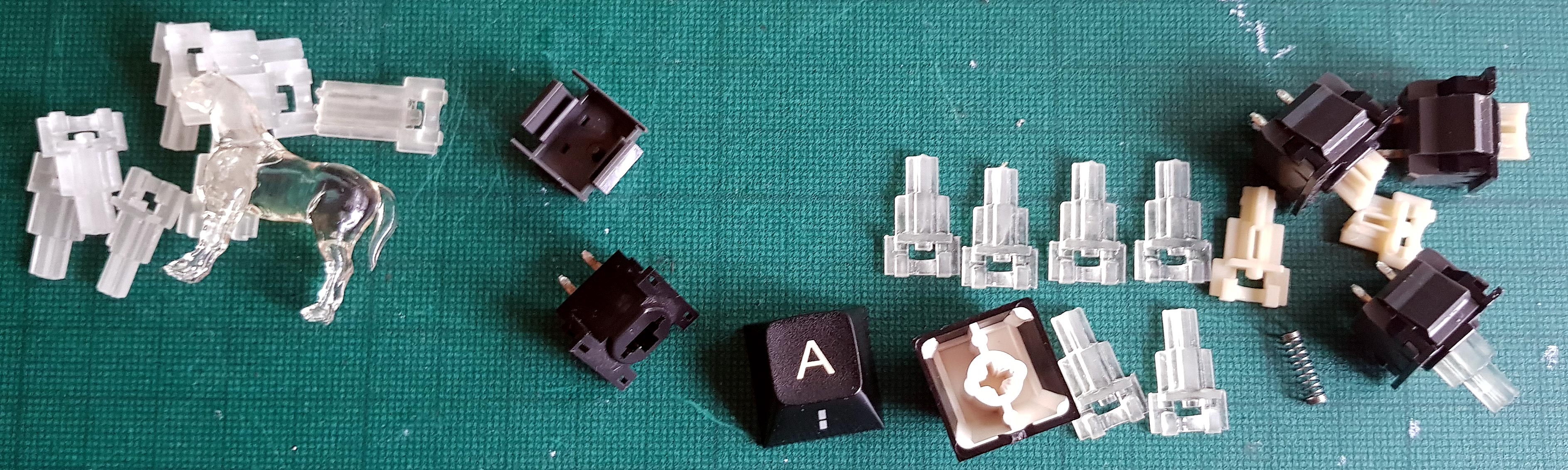
White ones are original, clear ones are new, 3D printed. It was quite hard to create a 3D model for this part as it is very small and has tons of details. But after four attempts I made it. On the left side of the image there are bad ones (the horse is also bad). Meanwhile on the right side there are some keys removed from the keyboard and disassembled.
Also, here is the STL file for this part. Take a note, that size of the key is ten times bigger (x10):
3D model in STL format for TI-99/4A keyboard key.
just scale the part to 10% and everything will be fine. Why? Because my 3D software is very buggy and only basic features are available. It is much easier to do bigger models in that software.
Whenever I talk about designers of the ZX Spectrum computer I use to say that they were smoking weed. Now I acquired one computer from another family of computers, TI99, I can tell that Texas Instruments designers not only smoked weed, but also used some heavy stuff. This is a crazy computer from an internal design view. Or maybe it was done on purpose- there was a big company behind pressing to use some obsolete chips to increase sales.
And there is the result:
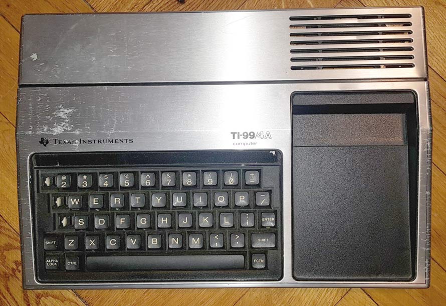
It is a Texas Instrument TI-99/4A computer, or maybe “console”- in all technical specifications it is called console.
I collected several ZX Spectrum series computers, but I don’t have any fancy peripherals. After several attempts I managed to buy ZX Spectrum Microdrive and interface 1 for it.
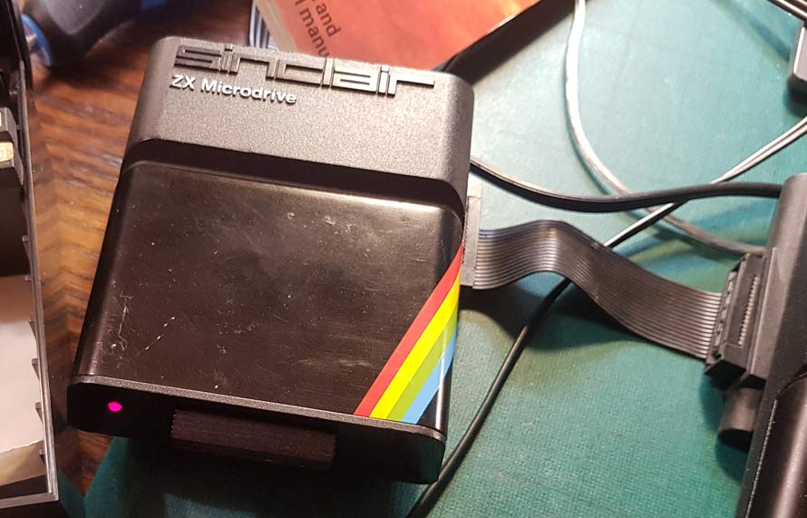
As always with ancient hardware it is working a bit, but in general not working: tape inside is moving, but nothing from the computer. The only problem, that to open this device I need to tear off the metal cover. According to original documentation, this metal cover is single use only. Now it is impossible to get new cover, so I gently took it off, but some deformation happened.
Continue reading