
First of all examine APC (American Power Conversion) LAN surge protector. It is removed from some APC UPS.
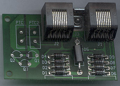
The circuit is very simple. Diodes D1-D4 and D6-D9 are IN4006. The D5 diode is more interesting. It is 1.5KE6.8CA. This is special diode: 1500 WATT PEAK POWER TRANSIENT VOLTAGE SUPPRESSOR.
Note J3. On PCB it is small gap between GND and signal wire.
In older telephone equipment special discharge devices are used for surge protection.
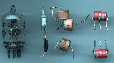
These devices are simple gas discharge tubes which can handle very high current for a short time. There single line protectors and protectors for symmetrical lines. We can use any of them in LAN protection.
One note to schematics. One side of line is directly grounded. In some cases, cable grounding must be done using some discharge device. Especially if the cable can be grounded in both sides. This will stop residual current in the cable.
Note: Grounding must be real! It must be real earth connection.
Here you can see discharge in the bulb:
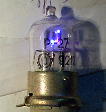
BTW, high voltage generated by welder ignitor. P-27 gas discharger specifications: ignition voltage 310…390V, Resistance 5*103 Mega ohms, max pulse current 2000A, constant current 2A, max pulse width 50…60μs, max frequency of pulses 50Hz.
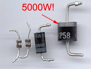
5KP58: 5000W Transient voltage suppressor, (58V, 400A)
1N5908: Unidirectional diode, peak pulse power 1500W (10/1000mks), reverse stand off voltage 5V. The 1N5908 and SM5908 are dedicated to the 5 V logic circuit protection (TTL and CMOS technologies). Their low clamping voltage at high current level guarantees excellent protection for sensitive components.
BR211-140: Breakover diodes. Breakover voltage 140V, pulse 40A. A range of bidirectional, breakover diodes in a two terminal envelope.Typical application is transient overvoltage protection in telecommunications equipment.
Pingback: Savel brain dump in English! » Blog Archive » UTP lightning protection
did you design the pcb ? if so can i use your trace art ?
No. I didn’t design PCB. This PCB is removed from APC UPS.
Very usefull. I replaced the 1N4006 diodes for others BY399.
good site you have. how much is the J3 gap?
any 🙂
0.5mm is quite good. As real sparks greater that 1kV will jump over this gap.
can you explain how this surge protector is working?
lightning causes tremendous EMI. This EMI generates quite high voltages in any cables. Without protection, these voltage spikes kills nearby electronics. Meanwhile, using this protector, voltage spikes rectified with multiphase rectifier made on simple diodes are absorbed by transil. Normal working voltages are too low to open pn connection on silicon diode and all lines are disconnected. Then only problems may be from small capacitance of diodes.
Static charges are removed using gass discharge devices.
This protector will not help with direct lightning to device… with direct shot nothing will help.
i wanna use this prototype for 20 ethernet switches. when the weather is snowing and raining with lightnings, some ports from 2, 3 switches crash. This is happing when outside is thunder. So if i use this prototype the switches will be safe?
i am quite a little electronic man, i studied today the tvs diode, i think this idea is good, but the tvs diodes are quite expensive, and i will buy them only if this prototype will protect my switchs. so i will be protected?
and what is that j3? it is like a disparty of the ground circuit from the diode circuit? and when the voltage level is above 1kv will appear a electrical arc ? and the spikes will discharge by it from the diode circuit to the ground?
I am using some modules removed from profesional rack- it is same schematics. It is 8 UTP channels at once. So I placed these modules at my workplace- we have quite long LAN lines over the buildings. During summer storm all lines were OK, only one without protection- switch ports was burned :). Now all the line have these protections.
But I must note, that all my UTP lines are shielded.
I don’t have photo of the module, but it is made completely of SMD components.
As our company deal with electronics scrap, I salvaged about 20 or more of these modules. I was even selling them in my webshop (http://kromelis.savel.org )
I don’t understand why TVS diodes are expensive? It cost almoust same as simple bigger diodes.
As you can see from post date, some time passed. But I had only on switch failure from lighning during these years. And I am using about 15 swithes with long outdoor lines. I had even home network between neibghours, but now it is replaced with fibre optics internet connection… Yes, I live in small country where local telecom company give us fibre optics internet without limits. 🙂 minimum speed is 50mbits, max? I don’t know – something about gig. 😛
it is discharge gap. Better to be replaced with spark gap tube like in the post.
and how did you shield it ? utp have 4 pairs of twisted 2 cables, and there is a shirt wich enclothe all the 4 pairs, so i will have to put this shirt to ground right? and i will have to put it on the both sides ori just in one ?
It is standard FTP/STP cable. Check google or wiki.
http://en.wikipedia.org/wiki/Twisted_pair
ok thankss!!!! i will contact you if i have one more question =)) 😀 .. i have decided. i will build it !
where can i find those spark gap tubes?
and will this work for pppoe connexions?
http://ro.farnell.com/epcos/b88069x8091b502/2-electrode-surge-arrestor-90v/dp/2101612 can i use this for gap tube?
Yes, maybe, poe voltage is less than 50V and it will not open transil. Need to test.
Any discharge device with lower voltage break.
http://www.digikey.com/product-search/en/circuit-protection/gas-discharge-tube-arrestors-gdt/655426?k=discharge
Arrestors are usable only if you have lots of static. If you use shielded cable, you don’t need discharge, as everything is going to earth via shield.
Meanwhile, if you use unshielded twisted pair, have lots of snow, dust storms, then you need discharge devices.
hello.
I build the surge protector, and i installed on the place where the switchs get crash almoust every raining weather. and … surprize… the switch get crashed. i think the gap must be removed and replaced with a conection directly to ground ( tvs diode -> ground). the cable shield is connected to ground in one place, so i can’t explain why the switch get crashed. i build the surge protector like in the schematic.
make sure, that EMI do not get to switch via power lines. Same rules- high voltage spike in the PSU. Also, if it is old switch (long runtime), you may need to revise power capacitors of CPU and main board.
Even this switch was crap from the beginning:
http://blog.savel.org/2008/08/10/wrt54ggl/
After cap replacement it is still working!
no … the cap aren’t the problem. i have replaced the switch 1 mounth ago and it was a new one, so the problem is the gap. i build the gap from 2 cupper bar with the distance 0.5 mm between them. the firs bar is connected to diodes and the second bar is connected to ground. so if there is 0.5 mm between them , the circuit is not grounded. so … isn’t work . i’m right? i’m from romania … i think i didn’t understand the real meaning of “gap” …. gap = distance …. a broken circuit ?
“Sparc gap” is used only in emergency situations. Normal “work” when there is no static charge and direct hit, it is not used. Your problems maybe from EMI in power lines.
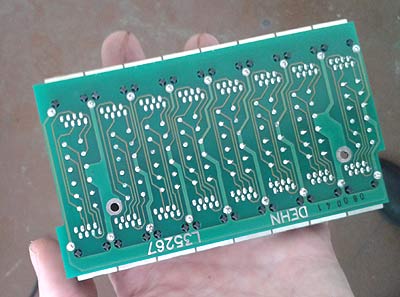
Photos of modules I use:

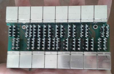
Eight LAN cables in module:
Circuit same, only there is no discharge gaps.
This module is placed in metal box, in abandoned building. You may notice PSU (not used in this case). This PSU is used in remote switches- it have posibility to add chargable lead battery to power switch even if power lines fail.
Black (upper) ccable is special outdoor cable with double insulation and steel cable molded to cable. It is used to join two nearby buildings without any aditional steel rope. The shield of this cable is connected to ground (the metal box), steel rope is grounded too. Meanwhile gray cable is not grounded, it is connected only to protection device. This is done to disable ground loop.
thanks … so you advice me not to use “spark gaps” or “gas tubes”. you advice me to replace the J3 gap with a conection to ground or just connect the d5 to d9 without any ground. the switch that crashes about 3 days ago had crashed on the lan ports not on the PSU. i have a psu from 220v AC to 9v DC near the switch and is connected to 220 in 2 or 3m of cable. i realy apreciate that you are trying to explain me how this work … the realy reason that i don;t understant is because of language…. my english language is very bad 🙂 i use google translate :(:|
I have a question.
Can I use those cheap orange neon gas discharge lamps in your surge protector schematic?
I would prefer lamps instead of diodes, because the spark gap limits the the protection up to 1kV and that special diode is a bit hard to find. Those orange neon lamps fire up around 80V thus clamping the voltage at that value, which is just a bit above the operating voltages in the ethernet cable. Also in this design no spark gap is needed.
The MAIN difference from neon glow tube and arrester (discharge) tube is the internal resistance of the “open” tube. Also, the power safely dissipated in the tube. Cheap neons can handle only tents of watts. Meanwhile discharge tubes can handle kiloamps (and kW) for very short time.
But neon tubes will work with limitations.
Spark gap is achieved by PCB design.
Thank you for your answer.
So if I understand correctly, I should add some current limiting resistor before the neon lamp, that will not burn out.
I could add a piece of resistance wire.
I found a bunch of neon lamps, dirt cheap, 20 US cents per piece: Neon lamp 230V / 1,4mA, with 1/4W 100Kohm resistor.
So I need to cut a piece of resistance wire to match 100k ohms. This would also work with higher current since as the wire heats up, from the excess current, it’s resistance goes up.
By the way, great website. I subscribed and bookmarked it!
No. The neon bulb must sacrifice itself to save other equipment. If you limit current of the tube, excess voltage will flow to your device. Do not add any resistors.
I was telling, that internal resistance of glowing neon tube is much bigger compared to internal resistance of active surge tube. So, neon lamp is not very effective compared to real device.
Constant AC (50Hz) current max: 15+15A (limited by temperature)
Pulse current: 2500A
Voltage:300V
Capacitance: 5pF
Small modern:
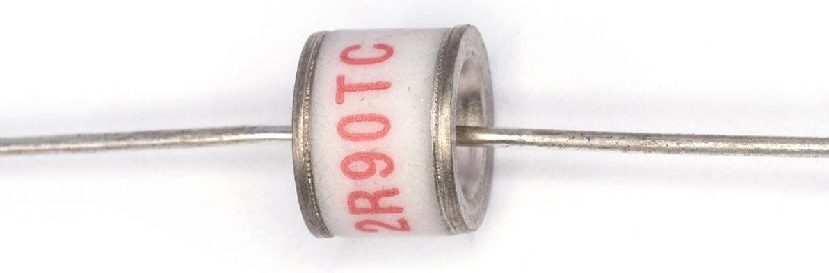
GDT1-86-2R-75L
Voltage: 75V
Capacitance: 2pF
Pulse current: 10-20kA
Constant current: 10A (limited by temperature, 0.2s)
Thank you, I realized my mistake.