
Sometimes I need small high voltage power supply for my projects. And I don’t want to make special transformers. And I don’t want to use special chips for it. In internet I found very simple circuit diagram for classical step-up converter. It is base on very common 555 timer. The coil used in this schematics is bought in the shop.
Here is the schematics:
Press for bigger image, for printing.
Some comments about this circuit diagram: I needed about 200V DC. During tuning I saw voltages going from Vin up to the voltage dangerous for diode, capacitor and mosfet. You only need to turn trimmer.
Theoretical values are printed in this circuit diagram, but during constructed I didn’t managed to collect exact values and used components from my spare part box.
So here is comments about replacement of components: First of all, T1 is MPSA42. Why author used high voltage transistor? Maybe he had lots of them. I don’t. The voltage here is only going to such level what 555 timer can handle- up to 18V. So I used more common transistor from computer power supply. It is C945 (50V, 0.1A, npn)
C9 capacitor is 100pF. C9 and R37 is typical snubber circuit, it filters out parasitic high frequency oscillations.
Trimmer R40 is 10K, R38- 470K. Diode D1 from old AT PSU, fast, high voltage diode FR154. L1 is from local hobby shop. They didn’t find any 100μH @ 1A, so I put 150μH.
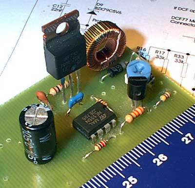
For my power, I didn’t need to put cooling radiator on Q1. Be careful, this device can shock you.