
You maybe noticed time gap in my weblog. I am constructing more complex device at this time and don’t have spare time for usual weblog entries. So I posted only few old re posts and some small note from “vandalising” theme.
My “great” project is seep generator with some additional features.
Final product will output: sweep signal in square, triangle and sin form. Also sweep generator can be used as wide band generator. Also, by adjusting few knobs the output can be transformed to sawtooth- left or right side.
The main device is still under construction, but some results can be posted here:
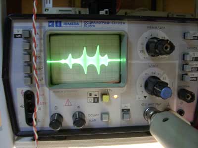
This is frequency characteristics of standard 455kHz ceramic filter. There is lack of detector and frequency marks, but something is showing. I can not tell that the output is right as I don’t have other equipment to test or compare the results.
Other features: the generator has the frequency modulation (FM) and pulse width modulation (PWM) inputs.
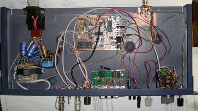
Everything is placed in low profile standard 19″ rack from some ethernet switch. The box is a bit to low, and I can’t place all outputs, buttons and knobs as I want.
The main circuit is not designed by myself. I used it from Russian magazine and internet site. The heart of the device is legacy chip MAX038. It is a pity, but this chip is no longer manufactured and newer will be. Internet rumours tells, that Maxim lost all design blueprints and device was manufactured off-site main Maxim factory.
The original circuit was based on old Russian and soviet parts, so I adapted the western devices as they are more available for me.
Also, I need to change my oscilloscope. Mine device didn’t have sawtooth output. In future, I have plans to place here circuit diagram and PCB design in Eagle format. Now I need to fix all errors I made in circuit and PCB. Almost all parts I used are SMD as I hate drilling holes.
Here is Original circuit from magazine.
Changes already made:
PSU: I changed PSU from +-12V to +-15V (As I have spare 7815 and 7915 chips), operational amplifiers: S4560 (thinking about using more fast in mark generator). I placed lots of ceramic and tantalum caps on power lines- I hate mains frequency hum and I have lots of them,
frequency setting capacitor in second frequency range is unipolar.
Main change: the sawtooth input. As my oscilloscope output is very weak I placed buffer and inverter. Now I have frequency change from left to right.
The PSU is very simple and not very good. I used simple linear regulators (I don’t want noise from switching ones) and transformer has only 2 outputs (19+19V, after rectifier). I used simple CL filter (2 x 2 x 2200uF). -5V is transformed from -15 circuit. But I can not used same schematics for +5V- too big load. So I used intermediate 12V regulator with heatsink, then I passed current to +5V regulator.
One more change: I used SMD 10MHz oscillator instead of crystal resonator and generator build from TTL logic elements. Less components, more stability and easy to build… 🙂